
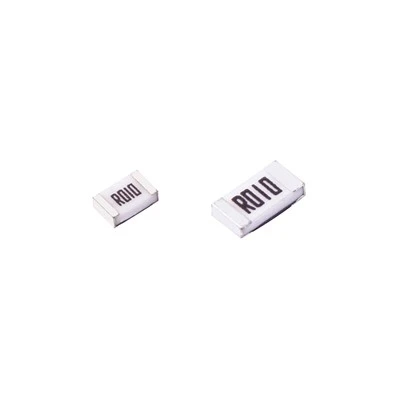
SMD 1206 Resistors
The 1206 thin film alloy resistor is made of metal film and ceramic substrate. Metal film is the use of high temperature vacuum coating technology to nickel-chromium or...

Metal Strip Current Sense Resistors
What is Metal Strip Current Sense Resistors
Eaton's metal plate resistors (also known as metal strip current sense resistors ) are constructed with a metal plate with epoxy overcoat and end terminations to provide low temperature coefficient of resistance (TCR), low resistance and high power capability.
Benefits of Metal Strip Current Sense Resistors
Low Inductance
Inductance is typically an unwanted property in resistors, particularly in filter circuits. All conductors have inductance, the value depends on its geometry. Generally a wide, flat and short geometry will have lower inductance than a thin, wound long conductor. This is where printed conductive ink allows resistor elements to be formed on wide flat ceramic insulating substrate. This delivers a very low inductance resistor.
Thick film resistors, with lower stray inductance, are therefore the preferred metal strip current sense resistors type for high frequency applications like PWM filters or current shunts.
Heat dissipation
Dissipating heat from a metal strip current sense resistors is all about surface area and the interface to a cooler medium. Thick film resistors enable a large flat surface area, meaning they are easy to attach to a heat sink or cold plate. Power dissipation of 2 kW is possible in 60mm square.
High Isolation voltage
A power resistor printed onto a ceramic substrate has an intrinsic isolation from the terminals to the base plate. This can be is enhanced with coatings (polyimide for example) applied to the resistor element. The ceramic substrate is then placed in a supporting mechanical housing which is filled with a silicone gel to complete the electrical isolation solution. Isolation rating of up to 12 kVrms to the baseplate can be achieved in a range of ultra high power resistors.
Robust construction
Thick film metal strip current sense resistors are more mechanically robust than wirewound resistors, which makes them less susceptible to damage as a result of poor handling or packaging, or rough insertion into a system.
Further, their construction involves constructive paint being screen printed and fired onto an insulating substrate, usually a ceramic base, making it a permanent assembly. This construction makes the resistors better at dealing with high power surges than their wirewound counterparts.
The ceramic layer – with the resistor printed onto it – is housed in a custom designed plastic case for protection, which also can incorporate mounting hardware. The housing also can have a spring installed to manage the pressure needed to reliably achieve good thermal contact without cracking the ceramics.
-
![SMD 1206 Resistors]()
-
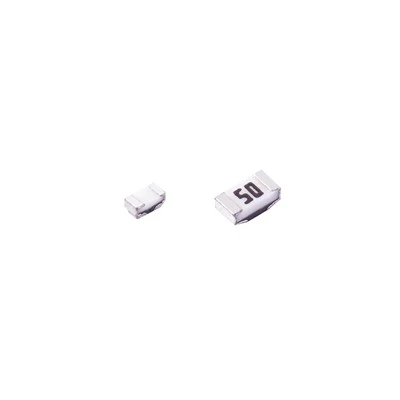
![SMD 0805 Resistors]() SMD 0805 ResistorsSMD 0805 Resistorsread more
SMD 0805 ResistorsSMD 0805 Resistorsread more
A metal strip current sensing resistor is a type of resistor used to measure the current in a circuit. They are usually composed of metal strips and resistive materials... -
![SMD 0603 Resistors]() SMD 0603 ResistorsSMD 0603 Resistors 10Rread more
SMD 0603 ResistorsSMD 0603 Resistors 10Rread more
A metal strip current sensing resistor is a type of resistor used to measure the current in a circuit. They are usually composed of metal strips and resistive...
Why Choose us
Quality services
Our team is committed to delivering high-quality services to our clients. We use the latest technologies and tools to ensure that our services exceed your expectations.
01
Quality
We offer high quality services and products that are relatable and resonate with your business needs.
02
Experience and expertise
Our company has been in business for many years and has amassed significant expertise and experience to provide quality services to our clients.
03
Competitive pricing
We offer competitive pricing for our services without compromising on quality.
04
Certifications and quality standards
Choose a factory that adheres to industry standards and certifications to ensure product safety and quality.
05
How To Use A Metal Strip Current Sensing Resistor
To measure resistance:
Turn power to circuit OFF.
• If a circuit includes a capacitor, discharge the capacitor before taking any resistance reading.
Turn digital multimeter dial to resistance, or ohms, which often shares a spot on the dial with one or more other test/measurement modes (continuity, capacitance or diode; see illustration below).
• The display should show OLΩ because, in Resistance mode, even before test leads are connected to a component, a digital multimeter automatically begins taking a resistance measurement.
• The MΩ symbol may appear in the display because the resistance of open (unattached) test leads is very high.
• When the leads are connected to a component, a digital multimeter automatically uses the Autorange mode to adjust to the best range.
• Pressing the Range button allows a technician to manually set the range.
• Best results will be achieved if the component to be tested is removed from the circuit. If the component is left in the circuit, the readings could be affected by other components in parallel with the component to be tested.
First insert the black test lead into the COM jack.
Then insert the red lead into the VΩ jack.
• When finished, remove the leads in reverse order: red first, then black.
Connect test leads across the component being tested.
• Make sure that contact between the test leads and circuit is good.
Tip: For very low-resistance measurements, use the relative mode (REL; see point 11). It may also be referred to as zero or Delta (Δ) mode. It automatically subtracts test lead resistance—typically 0.2 Ω to 0.5 Ω. Ideally, if test leads touch (are shorted together), the display should show 0 Ω.
Other factors that can affect resistance readings: Foreign substances (dirt, solder flux, oil), body contact with the metal ends of the test leads, or parallel circuit paths. The human body becomes a parallel resistance path, lowering total circuit resistance. Thus, avoid touching metal parts of test leads to avoid errors.
Read the measurement on the display.
When finished, turn the multimeter OFF to prevent battery drain.
Advanced digital multimeter options
Press the RANGE button to select a specific fixed measurement range.
• Be sure to note the annunciator (such as K or M) after the measurement in the display.
Press the HOLD button to capture a stable measurement—it can be viewed later.
Press the MIN/MAX button to capture the lowest and highest measurement.
• The multimeter beeps each time a new reading is recorded.
Press the relative (REL) button to set the multimeter to a specific reference value.
• Measurements above and below the reference value are displayed.

Metal Strip Current Sense Resistor Performance Specifications
Current sensing metal strip current sense resistors informationnumber of terminals- Most current resistors have either two or four terminals.
Resistance range - Resistance range is measured in ohms.
Tolerance - Tolerance is specified as percentage.
Power rating - Power rating is the maximum power level that a current sensing resistor supports.
Continuous operating voltage - The continuous operating voltage is measured in volts.Temperature coefficient parameter (TCP) - The temperature coefficient parameter (TCP) measures the rate at which the nominal resistance value changes as a function of temperature. Typically, TCP is expressed as parts-per-million per degree Celsius (ppm/C).
Operating temperature - Operating temperature is an important environmental parameter to consider, escially for current sensing metal strip current sense resistors which are exposed to flow, reflow, or wave soldering.
Metal Strip Current Detection Resistor Installation Method
Metal strip current sense resistors informationbolt-on to a chassis - By attaching solidly to a metal surface, these chassis-mounted resistors provide maximum heat dissipation.
Surface mount technology (SMT) - SMTadds current resistors to a printed circuit board (PCB) by soldering component leads or terminals to the top side of the board. Typically, the PCB pad is coated with a paste-like formulation of solder and flux.
Through-hole technology (THT) - Current sensing resistors that use THT are mounted on a PCB by inserting component leads through holes in the board, and then soldering the leads in place on the opposite side of the board.

How Do You Choose the Right Metal Strip Current Sense Resistors ?
Resistance value
This is the most important factor to consider when choosing a metal strip current sense resistors . The resistance value determines the amount of voltage drop across the resistor, which is proportional to the current flowing through it. For example, a 0.1Ω resistor will produce a 100mV voltage drop for every 1 Amp of current flowing through it.
Power rating
The power rating of a metal strip current sense resistors is the maximum amount of power it can dissipate without being damaged. It is essential to choose a resistor with a power rating that is high enough to handle the maximum amount of current that will flow through it.
Temperature coefficient
The temperature coefficient of a metal strip current sense resistors is the amount that its resistance value will change for every degree change in temperature. It is important to choose a resistor with a low-temperature coefficient to minimize the effects of temperature changes on the voltage drop across the resistor.
Tolerance
Tolerance is the amount a metal strip current sense resistors resistance value can vary from its nominal value. Choosing a resistor with a low tolerance is vital to ensure that the voltage drop across the resistor is as accurate as possible.
Types of Metal Strip Current Sense Resistors
Wire wound resistor
A form of a passive component is called a wire-wound resistor. A wire wound resistor is created by wrapping metal wire around a metal core. The metal wire serves as the electric current’s resistive component. Thus, the metal wire restricts a specific level of electric current. As a non-conductive substance, the metal core is placed. As a result, it blocks the flow of electric current.
Foil resistor
The most precise and reliable parts to employ to limit the flow of electric current to a specific level are foil resistors. Compared to other types of resistors, foil resistors generate little noise. The TCR (Temperature Coefficient of Resistance) of foil resistors is low.
Carbon composition resistor
A passive component that limits the flow of electric current to a set level is a resistor made of carbon called a carbon composition resistor. The cylindrical resistive element used to create the carbon composition resistors has integrated metal end caps. The ceramic and carbon powder combination is used to create the cylindrical resistive element of the carbon composition resistor. The carbon powder effectively conducts electric current.
Carbon film resistor
The carbon film resistor is the most common type of resistor used in electrical circuits. The carbon film is applied to a ceramic substrate to create the carbon film resistors. The ceramic substrate serves as an electrical current insulator, while the carbon sheet functions as a resistive element to the current.
Metal film resistor
A form of a passive component known as a metal film resistor uses metal film to limit the flow of electric current to a specific level. In contrast to metal film resistors, which use chromium, nickel, tin, and antimony to create their films, carbon is used to create the film in carbon film resistors. The TCR (temperature coefficient of resistance) of metal film resistors is low.
Metal glaze resistor
The metal glaze resistor is a passive component used to limit the flow of electric current to a certain level by combining glass powder with metal particles. Low TCR (temperature coefficient of resistance) for metal glaze resistors.
Metal oxide film resistor
A form of a passive component known as a metal oxide film resistor uses metal oxide film as the resistive element to limit the flow of electric current to a specific level. Metal oxide film resistor construction is virtually identical to metal film resistors.
Our Factory
The 1st team release high temperature Pt thin film sensor in Taiwan in1999
• The 1st team release current sensing resistor in Taiwan by lithography
process in 2000
• The 1st team release thin film high freq. chip inductor in size 0402 and 0603
in Taiwan in 2002
• Complete series of thin film resistor in size 0201 ~ 2512 in Taiwan in 2003
• The 1st team release thin film chip fuse in Taiwan in year 2004
• The 1st team release thin film ESD suppressor worldwide in 2005
• 1st team release thick film printing NTC thermistor in Taiwan in 2006
• The 1st team release thin film current sensing resistor in Taiwan in 2007
• The 1st team release Shunt CSR in Taiwan in 2012

Our Products

Asked Questions
As one of the leading metal strip current sense resistors suppliers in China, we warmly welcome you to buy discount metal strip current sense resistors from our factory. All customized products are with high quality and competitive price. For quotation and free sample, contact us now.
SMD 0805 Resistors 15R, SMD 1206 Resistors 10R, SMD 0603 Resistors 10R