


Product Parameter (Specification)
High isolation 5000 VRMS
DC input with transistor output
Operating temperature range - 55 °C to110 °C
REACH compliance
Halogen free (Optional)
MSL class 1
Regulatory Approvals
UL - UL1577
VDE - EN60747-5-5(VDE0884-5)
CQC - GB4943.1, GB8898
CUL- CSA Component AcceptanceService Notice No. 5A
|
ABSOLUTE MAXIMUM RATINGS |
||||
|
PARAMETER |
SYMBOL |
VALUE |
UNIT |
NOTE |
|
INPUT |
||||
|
Forward Current |
IF |
60 |
mA |
|
|
Peak Forward Current |
IFP |
1 |
A |
1 |
|
Reverse Voltage |
VR |
6 |
V |
|
|
Input Power Dissipation |
PI |
100 |
mW |
|
|
OUTPUT |
||||
|
Collector - Emitter Voltage |
VCEO |
80 |
V |
|
|
Emitter - Collector Volt |
VECO |
6 |
V |
|
|
Collector Current |
IC |
50 |
mA |
|
|
Output Power Dissipation |
PO |
150 |
mW |
|
|
COMMON |
||||
|
Total Power Dissipation |
Ptot |
200 |
mW |
|
|
Isolation Voltage |
Viso |
5000 |
Vrms |
2 |
|
Operating Temperature |
Topr |
-55~110 |
°C |
|
|
Storage Temperature |
Tstg |
-55~125 |
°C |
|
|
Soldering Temperature |
Tsol |
260 |
°C |
|
|
ELECTRICAL OPTICAL CHARACTERISTICS at Ta=25° |
||||||||
|
PARAMETER |
SYMBOL |
MIN |
TYP |
MAX |
UNIT |
TEST CONDITION |
NOTE |
|
|
INPUT |
||||||||
|
Forward Voltage |
VF |
- |
1.24 |
1.4 |
V |
IF=10mA |
|
|
|
Reverse Current |
IR |
- |
- |
10 |
μA |
VR=6V |
|
|
|
Input Capacitance |
Cin |
- |
10 |
- |
pF |
V=0,f=1kHz |
|
|
|
OUTPUT |
||||||||
|
Collector Dark Current |
ICEO |
- |
- |
100 |
nA |
VCE=10V,IF=0 |
|
|
|
Collector-Emitter Breakdown Voltage |
BVCEO |
80 |
- |
- |
V |
IC=0.1mA,IF=0 |
|
|
|
Emitter-Collector Breakdown Voltage |
BVECO |
6 |
- |
- |
V |
IE=0.1mA,IF=0 |
|
|
|
TRANSFER CHATACTERISTICS |
||||||||
|
Current Transfer Ratio |
TD827 |
CTR |
130 |
- |
400 |
% |
IF=5mA,VCE=5V |
|
|
Collector-Emitter Saturation Voltage |
VCE(sat) |
- |
0.06 |
0.2 |
V |
IF=20mA,IC=1mA |
|
|
|
Isolation Resistance |
RISO |
10^12 |
10^14 |
- |
Ω |
DC500V,40~60%R.H. |
|
|
|
Floating Capacitance |
CIO |
- |
0.4 |
1 |
pF |
V=0,f=1MHz |
|
|
|
Response Time(Rise) |
tr |
- |
6 |
18 |
μs |
VCE=2V,IC=10mA RL=100Ω |
3 |
|
|
Response Time(Fall) |
tr |
- |
8 |
18 |
μs |
3 |
||
|
Cut-off Fraquency |
fc |
- |
80 |
- |
kHz |
VCE=2V,IC=2mA RL=100Ω,-3dB |
4 |
|
Product Feature And Application
Computer peripheral interface
Microprocessor system interface
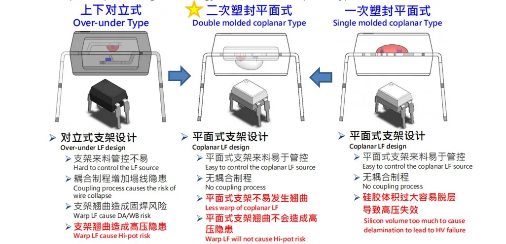
In terms of performance, it can replace Everlight EL827 LiteonLTV-827. CtmicroCT827. SharpPC827. ToshibaTLP521-2/621-2,CosmoKP1020. RenesasPS2501X-2/2521X-2/2561X-2/2571-2/2581-2VishayILD610/615/621, PanasonicCNZ3132, packaged in SMD8 and DIP8, with a CTR value of 130-400, is widely usedinhouseholdappliances, telecommunicationsequipment, systemequipment, switching power supplies, industrialcontrol, measurementinstruments, and signal transmission circuits for differentpotentials and impedances.
Prodection Details
DIP8 AC Optocoupler
Package Dimensions (Dimensions in mm unless otherwise stated)

Recommended Solder Mask (Dimensions in mm unless otherwise stated)

Prodect Qualification


Deliver, Shipping And Serving

Latest News


FAQ
1.The structure of 827 optocoupler?
Mainly composed of light-emitting diodes, photosensitive transistors, optocouplers, and packaging materials. Light emitting diodes and photosensitive transistors are responsible for the functions of light emission and photoelectric conversion, respectively. The optical coupling medium is used to isolate input and output signals, and the packaging material is used to protect the device.
2.The development history of optocouplers?
Optical Coupler (OCU) is an electronic component that utilizes optical signals to achieve electrical isolation. The development history of optocouplers can be briefly summarized as follows:
1. Early development: Optocoupler technology originated in the 1960s. The initial optocouplers used fluorescent materials as signal transmission media to convert electrical signals into optical signals, which were then converted back into electrical signals to achieve electrical isolation.
2. Universal application: In the 1970s, with the advancement of semiconductor technology, optocouplers underwent further development. Optocouplers using semiconductor materials such as LEDs and photodiodes have become widely used in various electronic devices, especially in situations that require high-voltage isolation or noise suppression.
3. Technical improvement: From the 1980s to the 1990s, the performance of optocouplers was significantly improved, including higher transmission rates, lower dark currents, and smaller packaging sizes. These improvements enable optocouplers to better meet the needs of data communication and computer interfaces.
4. Localization process: As mentioned earlier, China began researching light-emitting couplers in the late 1960s. With the passage of time and the accumulation of technology, domestic optocouplers have gradually become competitive in terms of performance and price, and have gained market recognition.
5. Modern applications: After entering the 21st century, with the trend of miniaturization and intelligence of electronic devices, optocouplers are also developing towards higher integration, lower power consumption, and faster transmission speed. Modern optocouplers are widely used in many fields such as power systems, industrial control, communication networks, medical equipment, etc.
In summary, the development history of optocouplers reflects the progress of electronic technology, and their unique advantages in isolation, anti-interference, and other aspects make them an important component of electronic product design. With the continuous innovation of technology, optocouplers will continue to play an important role in the future.
3.827 Application areas of optical coupling?
Power Systems: in power systems, 827 optocouplers are used to isolate signal transmission between high and low voltage circuits to ensure the safety of operators and equipment.
Communications equipment: in communications equipment, 827 optocouplers are used to isolate signal transmission paths to reduce signal distortion and interference. Automatic control system: in the automatic control system, 827 optocoupler is used to isolate the electrical connection between the control signal and the actuator to improve the stability and reliability of the system.
Instrumentation: in instrumentation, the 827 optocoupler is used to isolate the electrical connection between the measuring signal and the display device to ensure the accuracy of the measurement results.
4.827 What is the difference between optical coupling and other optical couplings?
827 optocoupler is a silicon-controlled drive output optocoupler, which is very common in high-speed data transmission and isolation applications. Compared with other couplers, 827 optocoupler has the following characteristics: output type: 827 optocoupler output is thyristor-driven, which makes it has advantages in high-speed switching applications. Other types of output may be different, such as transistor output, Darlington transistor output, etc. . High-speed performance: 827 optocoupler in high-speed data transmission performance, with a high transmission rate. Other couplers may be more commonly used in low-speed or medium-speed applications. Electrical parameters: there may be differences between 827 optocoupler and other optocouplers in some electrical parameters, such as transmission current, current transfer ratio (CTR) , forward voltage (VF) and so on. When choosing an optical coupler, it is necessary to ensure that these parameters meet the requirements of the circuit design.
5.How can the AC input triode be different from the DC input triode?
AC input triode and DC input triode are different in signal type and processing mode. They are all transistors with three electrodes, base (b), collector (c) and emitter (E) , but their applications and functions are different. AC input triode: AC input triode is mainly used to process AC signals. In this case, the base receives an AC signal input, the collector outputs an amplified AC signal, and the emitter is connected to the ground. The principle of AC input triode is based on the triode amplification characteristic, that is, the change of collector current can be controlled by the change of base current. AC input transistors are used in a variety of electronic devices and circuits, such as audio power amplifier and radio receivers. DC input triode: DC input triode is mainly used to process DC signals, such as switching power supply, regulated power supply and other circuits. In this case, the base receives the DC signal input, and the circuit is switched by controlling the on or off state between the collector and the emitter. The principle of DC input transistor is based on the switching characteristic of the transistor, that is, the change of the base voltage can control the on or off state between collector and emitter.
6.Why does the triode AC signal input or output have a positive or negative electrode?
If the triode amplification signal is emitter output, there is no reverse, the triode amplification signal output will be reverse-phase common emitter amplifier circuit, because the base signal changes caused by the collector current changes, for NPN tube, the base voltage is high, the collector current is large, and the large current produces a large voltage drop on the collector load resistance, which makes the collector output voltage low. And vice versa. Common collector circuit features: voltage gain less than 1 and close to 1, output voltage and input voltage in phase, high input resistance, low output resistance. Because the common-base circuit input circuit current for IE, and the output circuit current for IC, so no current amplification capacity. There is voltage amplification, and output voltage and input voltage the same, input resistance is smaller than common radio circuit, output resistance and common radio circuit equivalent, bandwidth.
Hot Tags: dip 8 ac optocoupler, China dip 8 ac optocoupler suppliers, 2835 620NM SMD LED 2V, for ELM453, SMD 1206 Resistors 10R, SMD 0402 Jumper 5 7A, SOP 4 Random Phase TRIAC, SMD 0603 Resistors 10R


