


Product Parameter (Specification)
Features
High isolation 5000 VRMS
DC input with zero-cross photo triac output
Operating temperature range - 40 °C to 100 °C
REACH compliance
Halogen free
MSL class 1
Regulatory Approvals
UL - UL1577
VDE - EN60747-5-5(VDE0884-5)
CQC - GB4943.1, GB8898
|
ABSOLUTE MAXIMUM RATINGS |
||||
|
PARAMETER |
SYMBOL |
VALUE |
UNIT |
NOTE |
|
INPUT |
||||
|
Forward Current |
IF |
60 |
mA |
|
|
Peak Forward Current |
VR |
6 |
V |
1 |
|
Reverse Voltage |
Tj R |
125 |
°C |
|
|
Input Power Dissipation |
PI |
100 |
mW |
|
|
OUTPUT |
||||
|
Off-state Output Terminal Voltage |
TD303X-4L |
VDRM |
250 |
V |
|
TD304X-4L |
400 |
|||
|
TD306X-4L |
600 |
|||
|
Peak Repetitive Surge Current PW=100μs, 120pps |
ITSM |
1 |
A |
|
|
Junction Temperature |
Tj |
125 |
°C |
|
|
Output Power Dissipation |
PO |
300 |
mW |
|
|
COMMON |
||||
|
Total Power Dissipation |
Ptot |
400 |
mW |
|
|
Isolation Voltage |
Viso |
5000 |
Vrms |
1 |
|
Operating Temperature |
Topr |
-40~100 |
°C |
|
|
Storage Temperature |
Tstg |
-55~150 |
°C |
|
|
Soldering Temperature |
Tsol |
260 |
°C |
2 |
|
ELECTRICAL OPTICAL CHARACTERISTICS at Ta=25° |
|||||||
|
PARAMETER |
SYMBOL |
MIN |
TYP |
MAX |
UNIT |
TEST CONDITION |
NOTE |
|
INPUT |
|||||||
|
Forward Voltage |
VF |
- |
1.24 |
1.4 |
V |
IF=10mA |
|
|
Reverse Current |
IR |
- |
- |
10 |
μA |
VR=6V |
|
|
Input Capacitance |
Cin |
- |
8.5 |
250 |
pF |
V=0,f=1kHz |
|
|
OUTPUT |
|||||||
|
Peak Off-state Current, Either Direction |
IDRM |
- |
- |
100 |
nA |
DRM=Rated VDRM IF=0 |
3 |
|
Peak On-state Current, Either Direction |
VTM |
1.59 |
2.5 |
V |
ITM=100mA |
|
|
|
Critical Rate of Rise of Off-state Voltage |
dV/dt |
1000 |
- |
- |
V/μs |
VPEAK =Rated VDRM |
4 |
|
TRANSFER CHATACTERISTICS |
|||||||
|
LED Trigger Current |
TD3031-4L,TD3041-4L, TD3061-4L |
IFT |
15 |
mA |
Terminal Voltage = 3VITM=100mA |
||
|
TD3032-4L,TD3042-4L, TD3062-4L |
10 |
||||||
|
TD3032-4L,TD3043-4L, TD3063-4L |
5 |
||||||
|
Holding Current |
IH |
- |
. |
237 |
. |
μA |
|
|
Isolation Resistance |
RISO |
10^12 |
10^14 |
- |
Ω |
DC500V,40~60%R.H. |
|
|
Floating Capacitance |
CIO |
- |
0.4 |
1 |
pF |
V=0,f=1MHz |
|
|
ZERO-CROSSING CHARACTERISTICS |
|||||||
|
Inhibit Voltage |
VINH |
- |
. |
20 |
V |
IF=Rated IFT |
3 |
|
Leakage in Inhibited State |
IDRM2 |
- |
. |
500 |
μA |
IF=Rated IFT VDRM=Rated VDRM |
4 |
Product Feature And Application
Solenoid/valve controls
Lighting controls
Motor controls
Temperature controls
Static AC power switches
Solid state relays
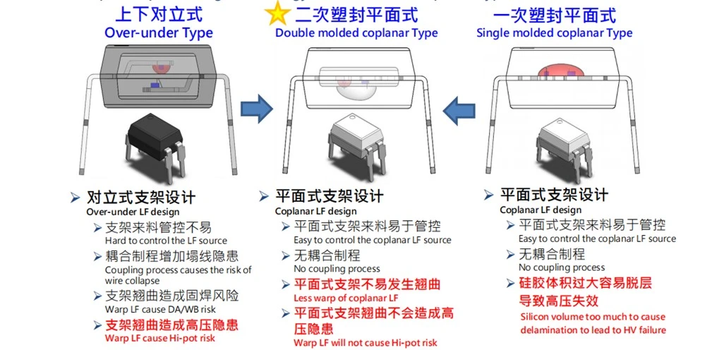
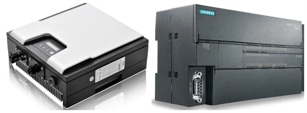
TD3063 for four foot zero-crossing trigger thyristor optocoupler,Divided into patches and plug-in two specifications,Isolation voltage 5000VRMS,The voltage is 600V and the trigger current is 5MA,The volume is 6.5 * 4.8 * 3.5 mm.
Prodection Details
DIP4 Zero Cross Optocouple
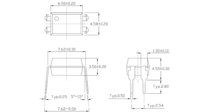
Package Dimensions (Dimensions in mm unless otherwise stated)
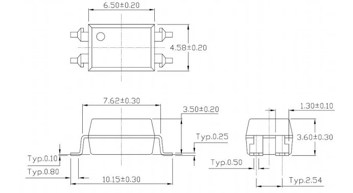
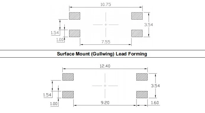
Recommended Solder Mask (Dimensions in mm unless otherwise stated)
Prodect Qualification
Deliver, Shipping And Serving

Latest News

FAQ
1.What are the main applications of silicon control?
Household Appliances: SCR is widely used in household appliances, such as electronic switches, air conditioners, refrigerators and so on. The stability and reliability of thyristor make its application in home appliances quite stable.Industrial electrical appliances: silicon-controlled silicon in the field of industrial electrical appliances also has a wide range of applications, such as resistive load, inductive load and transformer primary side. Silicon-controlled voltage regulator can be used for temperature control, temperature control of molten glass and other fields.
2.What is the main role of silicon-controlled optocoupler?
The use of bidirectional thyristor coupler to control the conduction of bidirectional thyristor, used to drive the motor, lamp source and other loads, and can achieve speed control and lighting functions. In the field of control and drive, bidirectional silicon-controlled optocoupler is widely used: high-speed air duct scheme, temperature control, motor control, incandescent lamp dimmer, AC power switch, solenoid valve control, etc.
3.The working principle of zero crossing optocoupler thyristor is?
The working principle of zero crossing optocoupler thyristor is to detect the zero position of the input AC power supply voltage through an optocoupler, and then control the power switch relay or thyristor to ensure that the device can conduct and turn off at zero crossing every time.
4.What should be paid attention to when using zero crossing optocouplers and thyristors?
In the application circuit of thyristor, common problems encountered are excessive peak opening current of thyristor, difficulty in rectifying EMI of the whole machine, etc. In practical applications, it is necessary to pay attention to the resistance value of the zero crossing optocoupler. If the resistance is too large, it will affect the accuracy of zero crossing acquisition; If the resistance is too small, the standby power consumption will be too high. Therefore, it is necessary to compromise the value based on the actual situation.
5.What is the difference between zero crossing optocoupler and randomly triggered optocoupler?
Zero crossing optocoupler thyristor is a bidirectional thyristor used for AC load regulation ci.
Hot Tags: dip 4 zero-cross optocoupler, China dip 4 zero-cross optocoupler suppliers, for EL354N, DIP 4 High Voltage Transistor, for TLP181, for LTV 354, Infrared LED, 2835 810 NM SMD LED 2V


