


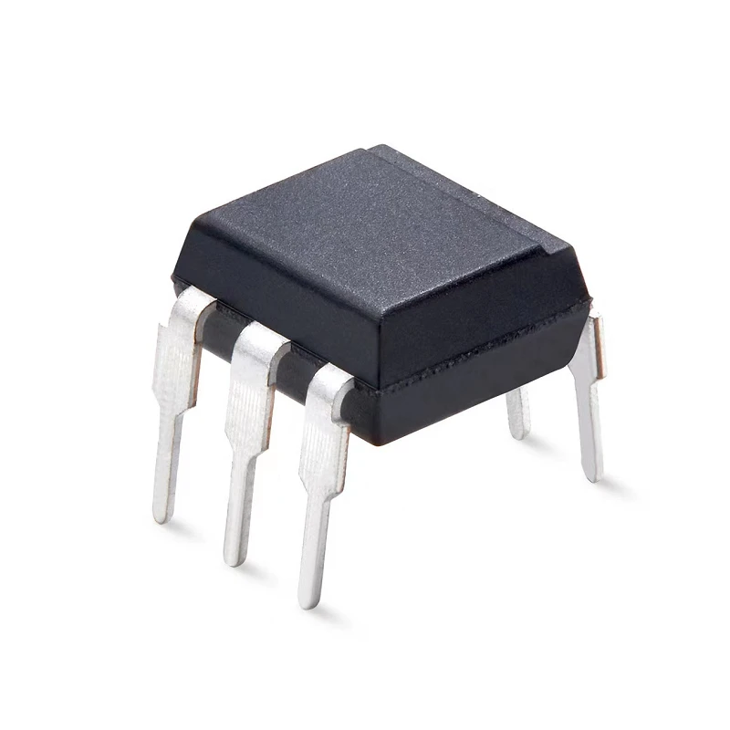
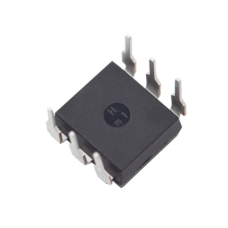
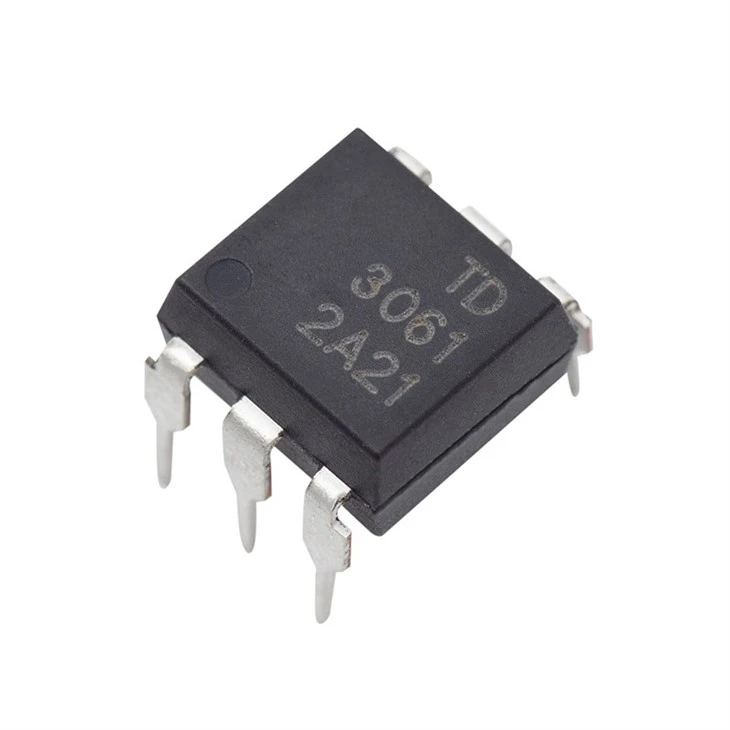
Product Parameter (Specification)
Features
High isolation 5000 VRMS
DC input with zero-cross photo triac output
Operating temperature range - 40 °C to100 °C
REACH & RoHS compliance
MSL class 1
Regulatory Approvals
UL - UL1577
VDE - EN60747-5-5(VDE0884-5)
CQC – GB4943.1, GB8898
|
ABSOLUTE MAXIMUM RATINGS |
|||||
|
PARAMETER |
SYMBOL |
VALUE |
UNIT |
NOTE |
|
|
INPUT |
|||||
|
Forward Current |
IF |
60 |
mA |
|
|
|
Reverse Voltag |
VR |
1 |
A |
||
|
Junction Tempera |
Tj |
125 |
°C |
|
|
|
Input Power Dissipatio |
PI |
100 |
mW |
|
|
|
OUTPUT |
|||||
|
Off-state Output Terminal Volta |
TD303X |
VDRM |
250 |
V |
|
|
TD304X |
400 |
||||
|
TD306X |
600 |
||||
|
Peak Repetitive Surge Current PW=100μs, 120pp |
ITSM |
1 |
A |
|
|
|
Junction Temperature |
Tj |
125 |
°C |
|
|
|
Output Power Dissipation |
PO |
300 |
mW |
|
|
|
COMMON |
|||||
|
Total Power Dissipation |
Ptot |
400 |
mW |
|
|
|
Isolation Voltage |
Viso |
5000 |
Vrms |
2 |
|
|
Operating Temperatur |
Topr |
-40~110 |
°C |
|
|
|
Storage Temperatur |
Tstg |
-55~125 |
°C |
|
|
|
Soldering Temperature |
Tsol |
260 |
°C |
|
|
|
ELECTRICAL OPTICAL CHARACTERISTICS at Ta=25° |
||||||||
|
PARAMETER |
SYMBOL |
MIN |
TYP |
MAX |
UNIT |
TEST CONDITION |
NOTE |
|
|
INPUT |
||||||||
|
Forward Voltage |
VF |
- |
1.24 |
1.4 |
V |
IF=10mA |
|
|
|
Reverse Current |
IR |
- |
- |
10 |
μA |
VR=6V |
|
|
|
InputCapacitance |
Cin |
- |
8.5 |
250 |
pF |
V=0,f=1kHz |
|
|
|
OUTPUT |
||||||||
|
Peak Off-state Current, Either Direction |
IDRM |
- |
- |
100 |
nA |
VDRM=RatedVDRM IF=0 |
3 |
|
|
Peak On-state Current, Either Direction |
VTM |
- |
1.59 |
2. |
V |
ITM=100mA |
|
|
|
Critical Rate of Rise of Off-state Voltage |
dV/dt |
1000 |
- |
- |
V |
VPEAK=RatedVDRM |
4 |
|
|
TRANSFER CHATACTERISTICS |
||||||||
|
LED Trigger Curren |
TD3031,TD3041,TD3061 |
IFT |
- |
15 |
mA |
Terminal Voltage = 3V ITM=100mA |
|
|
|
TD3032,TD3042,TD3062 |
- |
- |
10 |
|
||||
|
TD3033,TD3043,TD3063 |
- |
- |
5 |
|
||||
|
Holding Current |
IH |
- |
237 |
- |
μA |
|
||
|
Response Time(Rise) |
Ton |
- |
30 |
- |
μs |
IF=20mA,VD=9V,RL=100Ω |
||
|
Isolation Resistance |
Riso |
10^12 |
10^14 |
- |
Ω |
DC500V, 40 ~ 60% R.H. |
||
|
Floating Capacitance |
CIO |
- |
0.4 |
- |
pF |
V=0, f=1MHz |
||
Product Feature And Application
Solenoid/valve controls
Lighting controls
Motor controls
Temperature controls
Static AC power switches
Solid state relays
Interfacing microprocessors to 115 to
240VAC peripheral
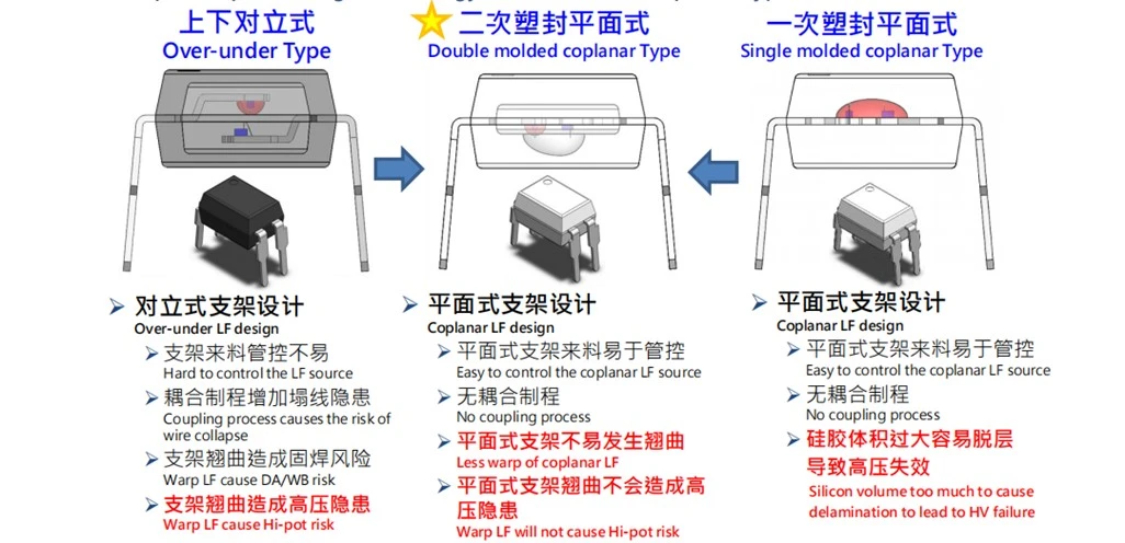
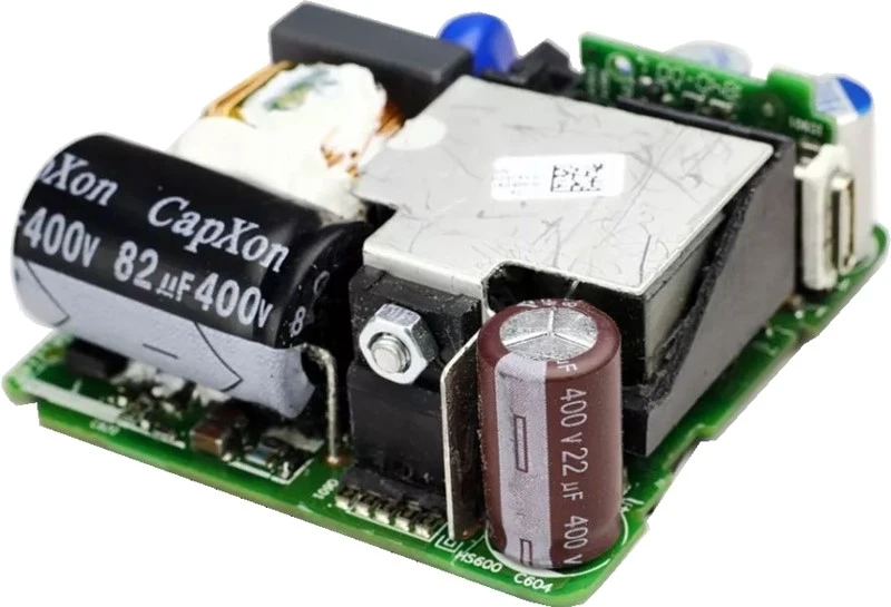
In terms of performance, it can replaceEverlightELM3061, Sharp PC3SG21YIZ0F, Toshiba TLP168J/163J/261J,CosmoKTLP161J/166J/168J, Fairchild FODM3062.
The bidirectional thyristor optocoupler can be used to control the conduction of the thyristor, which is used to drive loads such as motors and light sources, and can achieve functions such as speed regulation and dimming. In the field of control and drive,
thyristor optocouplers are widely used.
Prodection Details
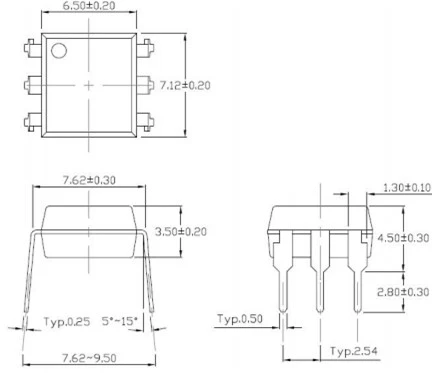
DIP6 Zero-CrossOptocouple
Standard DIP – Through Hole (DIP Type)
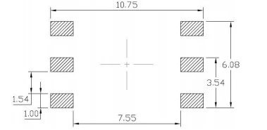
ESurface Mount Lead Forming & Surface Mount (Low Profile) Lead Forming Commended Solder Mask Dimensions in mm un
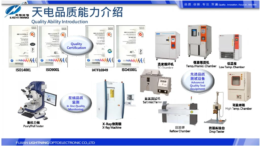
Prodect Qualification
Deliver, Shipping And Serving
Latest News

FAQ
1.The meaning of zero crossing triggering?
Zero crossing trigger is a method of controlling voltage or power by changing the number of cycles the thyristor conducts within a set time interval. The main disadvantage of zero crossing triggering is that low-frequency interference may occur when the on/off ratio is too small. When the power grid capacity is not large enough, phenomena such as lighting flicker and meter pointer jitter may occur. It is usually only suitable for electric heating loads with large thermal inertia.
2.The function of 3061 optocoupler?
Due to the mutual isolation between the input and output of the high-voltage optocoupler 3061, and the unidirectional transmission of electrical signals, it has good electrical insulation and anti-interference capabilities.
Due to the fact that the input terminal of the high-voltage optocoupler 3061 is a low resistance component that operates in a current mode, it has strong common mode suppression capability. So, as a terminal isolation element in long-distance transmission of information, it can greatly improve the signal-to-noise ratio.
3.3061 The special field of optical coupling?
3061 optocoupler is a commonly used optocoupler with good isolation performance and transmission characteristics. Although the 3061 optocoupler has been widely used in many fields, the following are some special applications:
Industrial control: In industrial control systems, the 3061 optocoupler is commonly used to achieve electrical isolation between various sensors and actuators, in order to improve system stability and safety. For example, in control systems such as PLC and DCS, the 3061 optocoupler can be used to isolate input/output signals.
Power Electronics: In power electronic equipment, the 3061 optocoupler can be used to achieve high-voltage and low-voltage electrical isolation to ensure the safe operation of the equipment. For example, in devices such as inverters and frequency converters, the 3061 optocoupler can be used to isolate control signals and power devices.
Communication system: In the communication system, the 3061 optocoupler can be used to achieve signal transmission and electrical isolation, in order to improve the system's anti-interference ability. For example, in fiber optic communication systems, the 3061 optocoupler can be used to isolate optical and electrical signals.
Medical equipment: In medical equipment, the 3061 optocoupler can be used to achieve electrical isolation and signal transmission to ensure the safety and reliability of the equipment. For example, in medical devices such as electrocardiographs and ultrasound devices, the 3061 optocoupler can be used to isolate electrical signals between patients and devices.
Automotive Electronics: In automotive electronic systems, the 3061 optocoupler can be used to achieve electrical isolation between various sensors and actuators, in order to improve system stability and reliability. For example, in automotive electronic devices such as engine control and braking systems, the 3061 optocoupler can be used to isolate input/output signals.
4.What should I pay attention to when using the 3061 optical coupling?
When using the 3061 optocoupler, pay attention to the following points:
(1). Correct connection: Connect correctly according to the circuit diagram of the 3061 optocoupler to ensure the polarity of the input/output signal is correct.
(2). Avoid overload: When using the 3061 optocoupler, avoid overload operation to avoid damaging the optocoupler.
(3). Regular inspection and maintenance: During the operation of the equipment, it is necessary to regularly check the working status of the 3061 optocoupler, and promptly identify and handle potential problems.
(4). Pay attention to heat dissipation: When using the 3061 optocoupler in high temperature environments, pay attention to heat dissipation measures to ensure that the optocoupler can operate within the normal temperature range.
(5). Comply with safety regulations: When installing and using the 3061 optocoupler, relevant electrical safety regulations must be followed to ensure personal and equipment safety.
5.How to properly install and test 3061 optocoupling?
When installing the 3061 optocoupler, please follow the following steps:
(1). Confirm the circuit diagram: Before starting the installation, please ensure that you are familiar with the circuit diagram and pin functions of the 3061 optocoupler. The 3061 optocoupler from different manufacturers may have different pin arrangements, so it is important to confirm the consistency of pin function and circuit diagram before installation.
(2). Preparation tools: You need a thin and pointed soldering iron (with a temperature of about 300-400 ℃), flux, and soldering wire.
(3). Cleaning pads: Use alcohol or soldering flux to clean the pads on the circuit board, ensuring that the surface of the pads is clean, free of oxides and dirt.
(4). Positioning optocoupler: Place the 3061 optocoupler correctly on the solder pads on the circuit board. Ensure that the pins of the optocoupler are aligned with the solder pads on the circuit board.
(5). Welding: Use a soldering iron to solder each pin of the optocoupler to the solder pads on the circuit board. During the welding process, ensure that the spacing between pins is appropriate to avoid short circuits.
(6). Inspection: After welding is completed, use a multimeter to check for short circuits or open circuits between the pins of the optocoupler. If there are any problems, please adjust or replace the optocoupler in a timely manner.
When testing the 3061 optocoupler, please follow the following steps:
(1). Preparation tools: You need a stable DC power supply (5V or 12V), a multimeter, and some resistors
(2). Connect the test circuit: Connect the DC power supply, 3061 optocoupler, and multimeter together according to the test circuit diagram. The test circuit diagram may vary depending on the optocoupler model, please refer to the optocoupler's data manual.
(3). Power on test: Connect the DC power supply and observe the reading on the multimeter. If the optocoupler is working properly, the reading of the multimeter should meet the parameter requirements in the data manual.
(4). Power off test: Disconnect the DC power supply and observe the reading on the multimeter. If the optocoupler is working properly, the reading of the multimeter should meet the parameter requirements in the data manual.
(5). Reverse voltage test: Apply reverse voltage to the input end of the optocoupler and observe the voltage change at the output end. If the optocoupler is working properly, the output voltage should meet the parameter requirements in the data manual.
(6). Temperature test: Place the optocoupler in different temperature environments and observe its performance at different temperatures. If the optocoupler works normally, its performance at different temperatures should meet the parameter requirements in the data manual.
Attention: During the testing process, electrical safety regulations must be followed to ensure personal and equipment safety. If you are not familiar with the testing process, please seek professional assistance.
6.What is the difference between thyristor optical coupling and ordinary optical coupling?
There are some differences in structure and function between thyristor optocouplers and ordinary optocouplers (also known as optocouplers or optoisolators). Here are their main differences:
(1). Component composition: The thyristor optocoupler is composed of a light-emitting diode and a photosensitive thyristor (photo triggered thyristor), while the ordinary optocoupler is composed of a light-emitting diode and a photosensitive transistor (phototransistor).
(2). Output characteristics: The output characteristics of the thyristor optocoupler are switch type, that is, the output terminal conducts when there is an optical signal input, and cuts off when there is no optical signal input. The output characteristics of ordinary optocouplers are linear, that is, the current at the output end is directly proportional to the strength of the input optical signal.
(3). Isolation voltage: Thyristor optocouplers typically have high isolation voltage capabilities, up to several thousand volts, suitable for high-voltage environments. However, the isolation voltage capability of ordinary optocouplers is relatively low, usually below a few hundred volts.
(4). Application field: Thyristor optocouplers are mainly used in power electronic equipment, industrial control systems, and other situations that require switch type signal isolation. Ordinary optocouplers are mainly used in communication equipment, household appliances, and other situations that require linear signal isolation.
(5). Response speed: The response speed of thyristor optocouplers is relatively fast, usually ranging from tens of nanoseconds to hundreds of nanoseconds. The response speed of ordinary optocouplers is relatively slow, usually ranging from a few nanoseconds to tens of nanoseconds.
In summary, there are certain differences in structure and performance between thyristor optocouplers and ordinary optocouplers, and suitable models should be selected based on specific application environments and performance requirements.
Hot Tags: dip 6 zero-cross optocoupler, China dip 6 zero-cross optocoupler suppliers, for HCPL 260L, SOP4 AC Optocoupler, for LTV M50, Darlington Transistor Optocoupler, Infrared LED, SMD 1206 Jumper


